Throwing Gauge
This throwing gauge is designed to be laser-cut from 6mm plywood. Please read the instructions and then click the download buttons at the bottom of this article. - It’s free, and there is a bit of work involved!
You will need to glue and cramp together several components.
Some wing-nuts and bolts are required (links below).
A small amount of wood must be removed from the end of each pointer arm (chisel and mallet required).
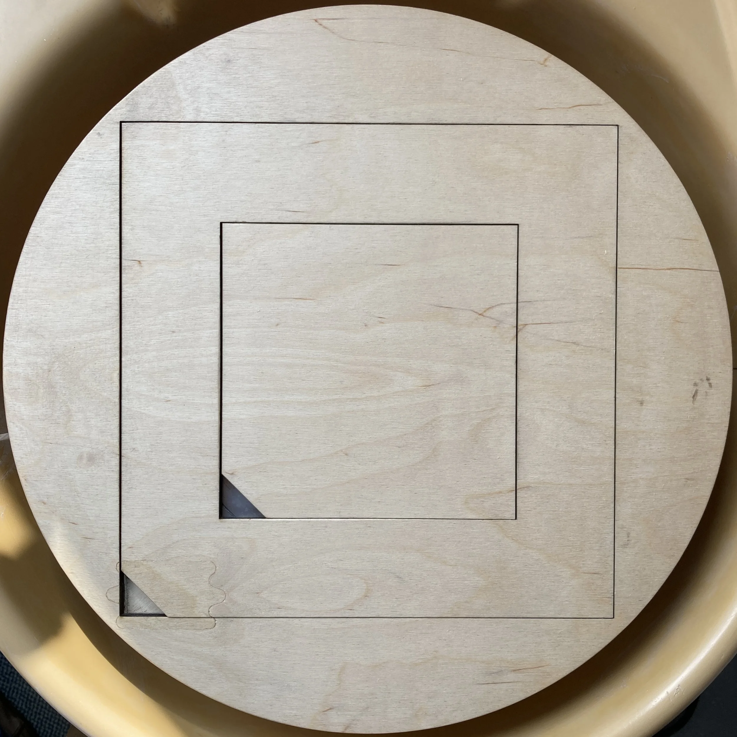
component to be cut and assembled
In the DXF files (which should be recognised by most laser-cutting software) the red lines are to be cut right through, and the blue lines are to be etched/drawn into the surface as a guide for later hand work. (The picture above shows you what to expect.)
The vertical post is made from 3 layers of 6mm ply (these are the top 3 components in the laser-cutter file). One tip here is to use the M6 bolts and wing-nuts to help align each of the 3 post components. Tighten these down and also use cramps to ensure a good bond.
Once these are joined, and the glue is dry, the 3 squares can be glued together to form the base. I recommend gluing the base AND fixing the vertical post in at the same time, so as to align everything correctly. The post may need to be tapped into the hole with a hammer (it should be quite a tight fit).
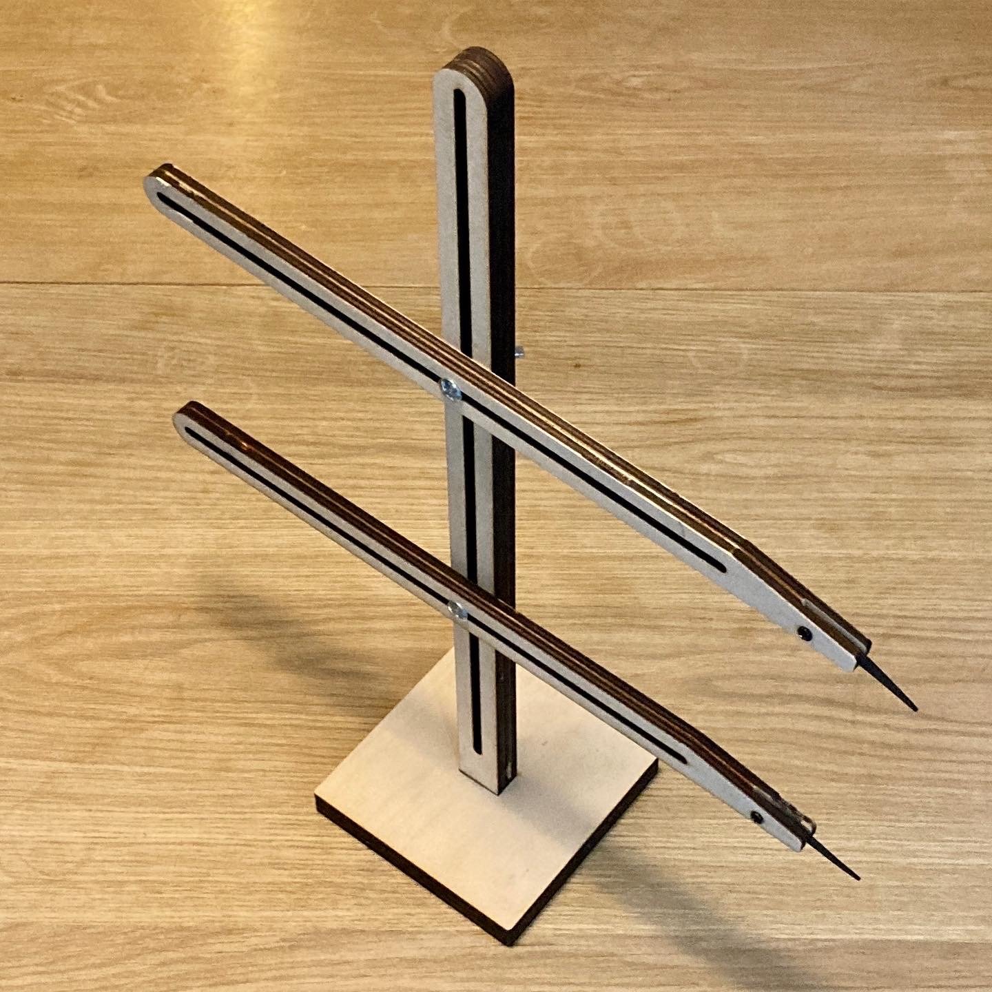
Each pointer arm is laminated from 2 components (each arm will be 12mm thick once complete). Before you stick these together, the end of each of these 4 components needs to have a sliver of the plywood removed using a chisel and mallet. (the pointers will be fixed in here and will pivot back as needed, so the thickness of your pointer material needs to be removed.) More about this below, but take your time on this step and plan it out.
In my case, I cut the pointers from 1.5mm thick rubber sheeting (it’s a bit too thin really, as you can see from how bendy it is the second photo below). I cut away about 1.5mm (a couple of ply laminations) from the end of each side of the pointer arm, allowing a 3mm gap for the pointer to pivot in. In the first photo below you can see the blue lines which show where to cut to, and in the fourth photo you can see that the pointer can rest upright if you follow these guide lines and cut the slots correctly.


OK, with the slots cut and the pointer arms joined, you will need some hardware to bolt it all together:
When you fix the rubber pointers on their pivot, you may decide to cut the M3 bolts a bit shorter with a hacksaw. They are a tight fit and will self-tap into the holes with a screwdriver.
And now for the disclaimer… All of this is something to save you money, and relies on a bit of DIY knowhow. If you are making precision work and rely on this tool for your income, then you may decide it’s worth investing in a commercial alternative. The advice and files here are not a guarantee of success! I’m happy to hear your feedback and may be able to help a little by email or via Instagram Direct Messages, but I teach full-time, so can’t provide tech-support nor can I promise a prompt reply unfortunately..
There are two files to download, one for the 6mm ply parts, and one for the 2mm rubber pointers:
NOTE: .dxf files are not commonly viewable on most home PCs, but you can view the downloaded files at ShareCAD.org